- Ltc4358
- Ideal Diode Mosfet Circuit
- Ideal Diode Mosfet Cross Reference
- Ideal Diode Mosfet For Sale
- Ideal Diode Mosfet Controller

In general, we normally utilize several types of basic electrical and electronics components to build the circuits, that comprises of resistors, diodes, capacitors, transistors, IC (integrated circuits), transformers, Thyristors and so on. Let us think about diode which is a two fatal semiconductor solid state device, that shows nonlinear V-I characteristics and it allows the flow of current in one direction only. When the diode is in forward bias, it gives very low resistance. In the same way, it obstructs the current flow during reverse bias in which it gives very high resistance. The diodes are classified into different types based on the working principle and its characteristics, like Zener diode, LEDs, constant current diodes, generic diodes, varactor diodes, tunnel diodes, ideal diode, laser diodes, photo diodes, Peltier diodes, etc.
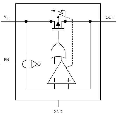
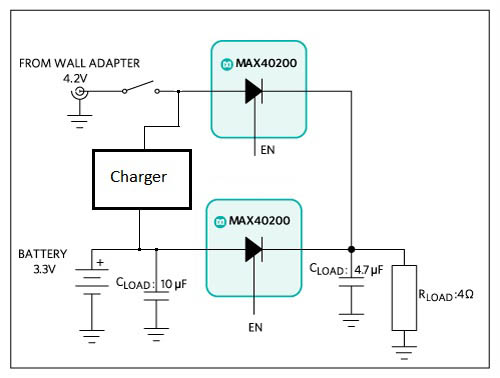
MOSFETs instead of one ideal diode MOSFET to prevent powering the load before the gate voltage of the ideal diode MOSFET ramps up. The LTC4229 provides voltage regulation to the ideal diode across the single ideal diode MOSFET or across three series connected components: ideal diode MOSFET, sense resistor, and Hot Swap MOSFET. Power diode 40V 600A with low forward voltage drop.
What is an Ideal Diode?
Re: Ideal diode MOSFET circuit « Reply #1 on: February 02, 2019, 06:47:39 am » Hi Barkuti, Yes, the circuit that you have designed is the full complement of the original circuit, so it will have the same characteristics as the original circuit, except all polarities will be reversed, as you show.
An ideal diode is one kind of an electrical component that performs like an ideal conductor when voltage is applied in forward bias and like an ideal insulator when the voltage is applied in reverse bias. So when +ve voltage is applied across the anode toward the cathode, the diode performs forward current immediately. When a voltage is applied in reverse bias, then ir performs no current at all. This diode operates like a switch. When the diode is in forward bias, it works like a closed switch. Whereas, if an ideal diode is in reverse bias, then it works like an open switch.
Ideal Diode Circuit Symbol
An ideal diode consists of two terminals like a normal diode. The connections of component’s end and terminals are polarized. It is important to know that not to combine the connections on a diode up. The two terminals of an ideal diode are called the anode and cathode where anode is positive and cathode is negative.
The circuit symbol of an ideal diode is a triangle shape against a line. There are different kinds of diodes are available in the market, but generally the symbol of the diode will look like the following diagram. The fatal entering the smooth edge of the triangle signifies the anode. The flow of current in the triangle direction is pointing, but it cannot go the other way.
Ideal Diode Circuit
As discussed in the above, ideal diode is the simplest device. The circuit symbol for an ideal diode is shown in the above and demonstrates its two-terminal nature. Download adobe photoshop elements 11 for mac. This means, that there are two terminals to attach the diode to the exterior circuit, namely the anode and cathode. The anode terminal is more positive than the cathode terminal and the flow of current will be in the direction specified.
The below circuits are the examples of a couple of simple ideal diode circuits. In the first circuit, the D1 diode is forward biased and permitting the flow of current through the circuit. So, its look like a short circuit. Whereas in the second circuit, the D2 diode is connected in reverse bias, the flow of current cannot flow in the circuit, and it basically looks like an open circuit.
Ideal Diode Characteristics
The current-voltage characteristic is the most important relationship for the diode. That defines how the current flows through the component and how the voltage is measured across it. The i-v arc of an ideal diode is entirely non-linear. It looks something like the following graph.
Threshold Voltage
Ltc4358
Ideal diodes do not have a threshold voltage. Once any forward voltage is applied across the diode, it will conduct current instantly across its junctions
Ideal Diode Mosfet Circuit

Forward Current
Ideal diodes include unlimited forward current when any forward voltage is applied across their terminals. This is due to the ideal condition, the inner resistance of the diode would be zero. The ideal diode would have no inside resistance at all. Since current (Ohms Law I=V/R), an unlimited amount of current would be performed and supplied to an electrical circuit with an ideal diode.
Breakdown Voltage
Ideal diodes do not have a breakdown voltage. This is because, the diode has unlimited resistance to reverse voltage. It will not perform any current at all when voltage is applied in reverse.
Reverse (leakage) Current
Ideal Diode Mosfet Cross Reference

Ideal Diode Mosfet For Sale
As an ideal diode does not contain a breakdown end, it never performs any reverse current termed leakage current. It is an ideal insulator when voltage is applied in reverse. Microsoft office x for mac download.

Ideal Diode Mosfet Controller
Thus, this is all about ideal diode and its characteristics. We hope that you have got a basic information regarding this concept. Furthermore any doubts or to know the types of diode, please give your feedback by commenting in the comment section below. Here is a question for you, What is the difference between ideal diode and conventional diode?
